
Iteration of PACK Protection Solutions: From Passive Protection to Intelligent Safeguarding
The external short-circuit protection scheme of energy storage battery systems is a critical aspect of system design. Currently, the mainstream solution relies on fuses for short-circuit protection, utilizing their strong current-limiting characteristics to achieve rapid interruption. Along with the evolution of energy storage PACK technology, protection schemes have also continuously evolved to meet new system requirements.
In the early stage of air-cooled PACK systems, the number of series-connected cells was relatively small and the rated voltage of a single PACK was low. Traditional 80V-rated fuses were used for protection inside the PACK. This stage lasted only for a short period, making it essentially a transitional solution in the industry.
To establish a more rational protection logic for energy storage systems, PACK fuses and high-voltage box fuses should satisfy selective protection coordination requirements, ensuring localized protection under different short-circuit scenarios. The fuse selection principle is:
High-voltage box fuse melting I²t < PACK fuse pre-arcing I²t
This principle has consistently remained throughout the development of the entire energy storage industry.
In summary, manufacturers comprehensively considered performance, size, cost, and failure risks, and therefore adopted 250V fuses rather than full-voltage 1500V fuses as the short-circuit protection solution inside PACKs.
In essence, whether 250V or 500V fuses were used, neither matched the full system voltage level.
Clause 7.9.11 of UL 1973-2022 explicitly states that the voltage rating of protective devices inside battery modules shall be determined based on the maximum system voltage. Consequently, during this stage of development, energy storage system manufacturers gradually started adopting full-voltage protection solutions using 1500V fuses, regardless of whether the system employed 52-series or 104-series PACK configurations.
In recent years, the energy storage industry has intensively introduced safety-related standards, placing explicit requirements on PACK overload, overcharge, and short-circuit test conditions:
Traditional Class “a” fuses, which rely on thermal melting principles for protection, find it difficult to achieve rapid interruption under low-current fault conditions.
To meet the requirements of overload, overcharge, and high-impedance short-circuit testing in energy storage PACKs, intelligent fuses are gradually being adopted in energy storage PACK applications.
First-Generation PACK Protection Solution
In the early stage of air-cooled PACK systems, the number of series-connected cells was relatively small and the rated voltage of a single PACK was low. Traditional 80V-rated fuses were used for protection inside the PACK. This stage lasted only for a short period, making it essentially a transitional solution in the industry.To establish a more rational protection logic for energy storage systems, PACK fuses and high-voltage box fuses should satisfy selective protection coordination requirements, ensuring localized protection under different short-circuit scenarios. The fuse selection principle is:
High-voltage box fuse melting I²t < PACK fuse pre-arcing I²t
This principle has consistently remained throughout the development of the entire energy storage industry.
Second-Generation PACK Protection Solution
The second-generation 52-series liquid-cooled PACK protection solution adopted 250V-rated fuses. Since each battery cluster in an energy storage system is composed of multiple battery PACKs connected in series, the overall system voltage is generally much higher than the PACK voltage. The main reasons why 250V fuses were widely used in 1500V energy storage systems are as follows:Industry Chain Considerations
Energy storage PACKs are only one part of the energy storage supply chain. As independent products supplied to downstream system integrators, PACK manufacturers mainly focused on PACK-level protection, resulting in PACK voltages being much lower than system voltages.Space Constraints
The internal space of a PACK is highly compact. Fuses are generally installed in the gaps between battery cells and end plates. Compared with 1500V fuses, 250V products offer significant advantages in size.Cost Considerations
250V fuses are considerably less expensive than 1500V fuses. Given the large quantity of PACKs used in a system, 250V products provide substantial cost advantages.Technical Considerations
Class “a” fuses are generally selected for short-circuit protection inside PACKs. When the short-circuit current is sufficiently high, the fuse pre-arcing time becomes very short, allowing several series-connected fuses to open simultaneously, thereby reducing the risk of interruption failure. However, it should be noted that when the short-circuit current is relatively low, the risk of inconsistent interruption among series-connected fuses increases.In summary, manufacturers comprehensively considered performance, size, cost, and failure risks, and therefore adopted 250V fuses rather than full-voltage 1500V fuses as the short-circuit protection solution inside PACKs.
Third-Generation PACK Protection Solution
Voltage Upgrade
As the series configuration of energy storage PACKs evolved from 52-series to 104-series, the increase in PACK voltage also drove the upgrade of fuse rated voltage. For reasons similar to those discussed above, 500V fuses began to be adopted in 104-series PACKs.In essence, whether 250V or 500V fuses were used, neither matched the full system voltage level.
Clause 7.9.11 of UL 1973-2022 explicitly states that the voltage rating of protective devices inside battery modules shall be determined based on the maximum system voltage. Consequently, during this stage of development, energy storage system manufacturers gradually started adopting full-voltage protection solutions using 1500V fuses, regardless of whether the system employed 52-series or 104-series PACK configurations.
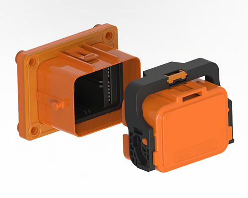
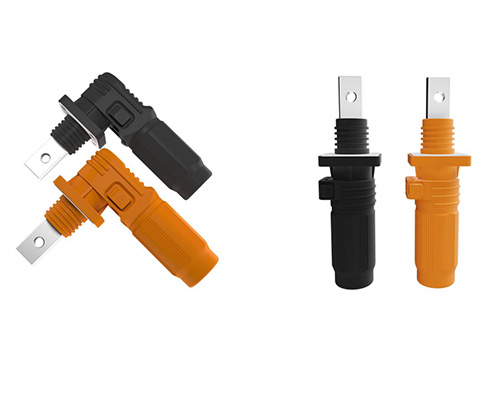
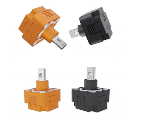
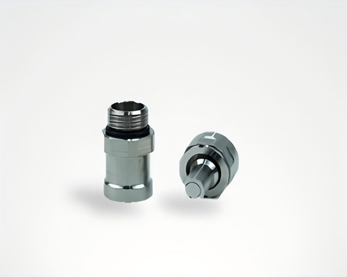
Installation Method Upgrade
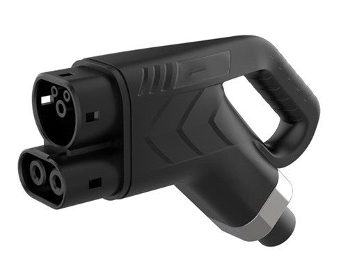
At this stage, in addition to bolt-mounted solutions, MSD (Manual Service Disconnect) installation methods also became increasingly common in energy storage PACK fuse applications. Although MSD installation provides easier maintenance, the enclosed internal structure results in relatively poor heat dissipation. Therefore, when selecting fuses, the temperature rise under MSD installation conditions must be carefully considered.Fourth-Generation PACK Protection Solution
As battery cell capacity evolved from 280Ah to 314Ah and now to 500Ah+, the capacity of individual PACKs has also continued to increase. Under the same discharge rate conditions, larger-capacity cells imply higher charge and discharge currents, requiring larger current protection devices. Consequently, energy storage PACK fuses have continuously expanded in capacity to meet the protection requirements of larger battery cells.In recent years, the energy storage industry has intensively introduced safety-related standards, placing explicit requirements on PACK overload, overcharge, and short-circuit test conditions:
- GB/T 36276-2023 Lithium-ion Batteries for Electric Energy Storage introduced a new 4P overload test. Battery PACKs are required to complete charging and discharging under 4P constant-power conditions. If fuses are installed inside the PACK, they must withstand the overload current without opening during the test. The standard also specifies clear requirements for PACK overcharge conditions.
- UN38.3 United Nations Manual of Tests and Criteria specifies a 55°C external short-circuit test, requiring the maximum total external resistance during testing to be 100mΩ.
- GB 44240-2024 Safety Requirements for Lithium Batteries and Battery Packs Used in Electrical Energy Storage Systems requires consideration of transportation and installation risks, including high-impedance external short-circuit testing.
- UL 1973 requires that the total resistance of the PACK and short-circuit device during short-circuit testing shall not exceed 20mΩ.
Traditional Class “a” fuses, which rely on thermal melting principles for protection, find it difficult to achieve rapid interruption under low-current fault conditions.
To meet the requirements of overload, overcharge, and high-impedance short-circuit testing in energy storage PACKs, intelligent fuses are gradually being adopted in energy storage PACK applications.
| PACK Generation | Period | Cooling Method | Cell Specification | Series Configuration | Protection Device | Voltage Rating | Protection Functions |
| G1 | 2019–2020 | Air Cooling | 280Ah | 16S / 24S | Traditional Fuse | 80V | Short-Circuit Protection |
| G2 | 2020–2022 | Liquid Cooling | 280Ah | 52S | Traditional Fuse | 250V | Short-Circuit Protection |
| G3 | 2022–2024 | Liquid Cooling | 314Ah | 104S | Traditional Fuse / MSD | 500V / 1500V | Short-Circuit & Overload Protection |
| G4 | 2024–Present | Liquid Cooling | 500Ah+ | 104S | Traditional Fuse / Intelligent Fuse | 500V / 1500V | Short-Circuit, Overload & Overcharge Protection |
Message
If you are interested in our products, please fill in the message form below. Our sales representative will contact you within 24 hours.