The High-Voltage Safety Lifeline of ESS: Standardized MSD Installation and Removal Procedures for Battery Strings
In today's liquid-cooled BESS, one operation is almost always involved during battery string installation, maintenance, or servicing—the installation and removal of the MSD, where applicable.
For large-scale energy storage systems operating at DC1000V to DC1500V, how should multiple MSDs within a battery string be installed and removed to minimize safety risks during operation?
This article provides a detailed analysis.
An MSD may incorporate a fuse internally (or use an external fuse arrangement) and enables operators to manually and quickly disconnect the high-voltage circuit without tools. By providing both electrical and mechanical isolation, it helps ensure personnel safety during maintenance, troubleshooting, and emergency situations.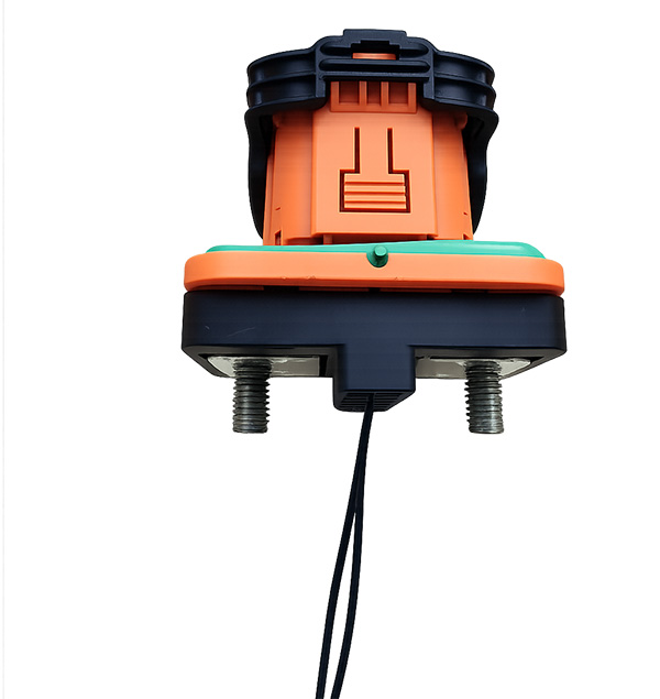
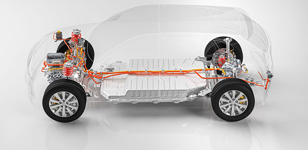
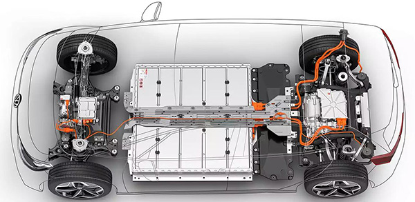
As energy storage systems have evolved toward higher voltages (up to DC1500V), larger capacities, and higher current ratings, especially with the widespread adoption of liquid-cooled battery packs, maintenance complexity and operational risks have increased significantly.
Compared with air-cooled battery packs, liquid-cooled packs generally feature higher capacity, higher voltage, greater energy density, and more demanding maintenance requirements. Consequently, MSDs have gradually become a standard safety component in mainstream liquid-cooled energy storage battery packs.
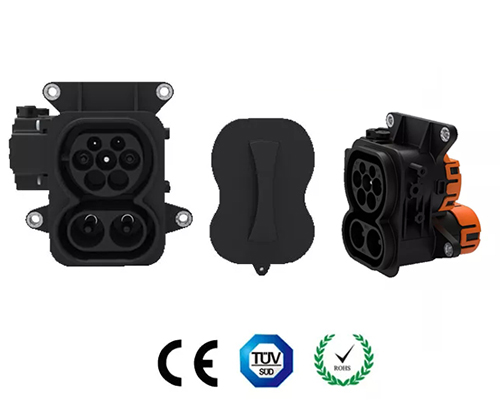
--Receptacle
The receptacle is typically connected in series with the positive circuit of the battery pack and generally includes:
◆Busbar terminals
◆Fixed high-voltage contacts
◆High-voltage interlock (HVIL) contacts
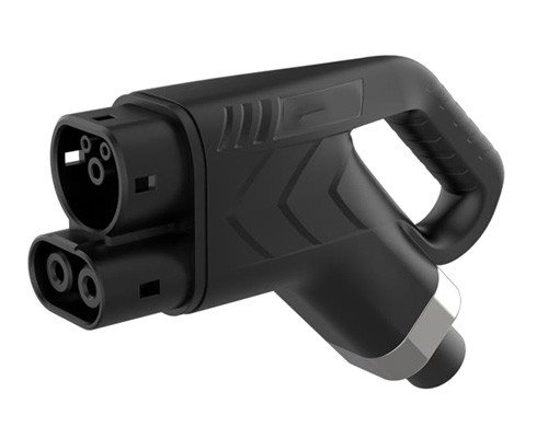
--Plug
The plug assembly typically includes:
◆Moving high-voltage contacts
◆HVIL actuation pin
◆Operating handle
◆Locking mechanism
During maintenance, electrical isolation is achieved by removing the MSD plug.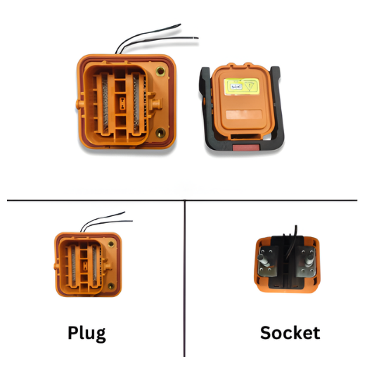
◆ Minimizing the risk of electric shock and short circuits during maintenance activities.
This is achieved through strict adherence to the principle of Potential Gradient Control.
◆ During Removal (De-Energization)
Operate progressively from the highest-potential point to the lowest-potential point.
The high-voltage source is disconnected first, and each subsequent step continuously reduces the maximum voltage present in the remaining circuit, thereby minimizing risk.
◆ During Installation (Energization Preparation)
Operate progressively from the lowest-potential point to the highest-potential point.
The high-voltage source is intentionally kept disconnected until the final step, ensuring that the voltage level at each operating point remains as low as possible throughout the process.
The overall electrical configuration is as follows:
String Positive Terminal (Highest Potential)→ Pack 1 Positive → MSD → Pack 1 Negative
→ Pack 2 Positive → MSD → Pack 2 Negative
→ Pack 3 Positive → MSD → Pack 3 Negative
→ Pack 4 Positive → MSD → Pack 4 Negative
→ String Negative Terminal (Lowest Potential / System Ground Reference)
→ Connected to the Negative Circuit of the High-Voltage Distribution Unit
Potential Distribution
Pack 1 > Pack 2 > Pack 3 > Pack 4
where Pack 1 is closest to the string positive terminal and Pack 4 is closest to the string negative terminal.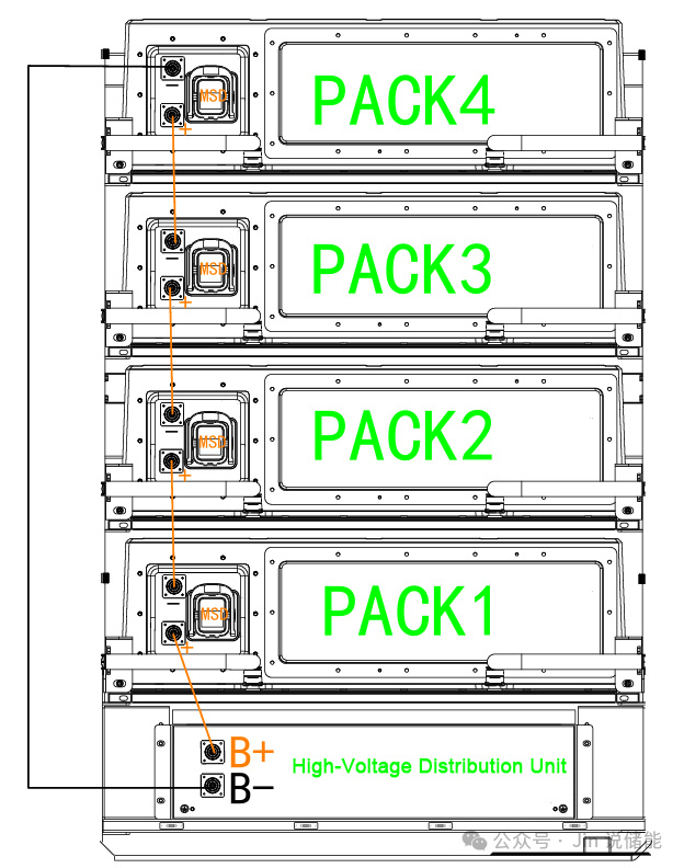
(Progressing from Low Potential to High Potential)
Step 1: Install the MSD plug of Pack 4 (closest to the string negative terminal and at the lowest potential).
Step 2: Install the MSD plug of Pack 3 and verify full contact engagement and latch locking.
Step 3: Install the MSD plug of Pack 2 and verify full contact engagement and latch locking.
Step 4: Install the MSD plug of Pack 1 (closest to the string positive terminal and at the highest potential), and verify full contact engagement and latch locking.
Why This Sequence Is Recommended?
▷ The High-Voltage Source Remains Disconnected Until the Final Step
By starting from the lowest-potential side, the complete high-voltage source remains isolated throughout the installation process.
Until the final MSD of Pack 1 is installed, the full DC1500V string voltage is never connected, keeping operational risk at the lowest possible level.
▷ Prevents Premature Formation of a High-Voltage Circuit
If installation begins from Pack 1 on the positive side, the high-voltage source may be introduced into the circuit prematurely.
Subsequent MSD installation operations would then be performed at elevated potentials. Any accidental tool-to-ground contact or unintended circuit closure could result in:
◆High-voltage short circuits
◆Unexpected energization
◆Equipment damage
◆Personal injury
▷ Ensures Proper HVIL Operation
Installing MSDs from low potential to high potential ensures that the HVIL circuit is not fully completed until all main power contacts are properly engaged.
This prevents premature HVIL closure, which could cause the Battery Management System (BMS) to incorrectly interpret circuit status and potentially energize contactors before all power connections are fully established.
(Progressing from High Potential to Low Potential)
Step 1: Remove the MSD plug of Pack 1 (highest potential).
Step 2: Remove the MSD plug of Pack 2.
Step 3: Remove the MSD plug of Pack 3.
Step 4: Remove the MSD plug of Pack 4 (lowest potential).
Why This Sequence Is Recommended?
▷ Immediate Isolation of the High-Voltage Source
Removing the MSD closest to the string positive terminal immediately disconnects the highest-voltage source within the battery string.
With each subsequent MSD removal, the maximum voltage remaining in the circuit decreases by one battery pack voltage level, continuously reducing operational risk.
▷ Prevents High-Voltage Floating Conditions
If removal begins from Pack 4 on the negative side, the entire series-connected battery string may become electrically floating relative to system ground.
As a result, all subsequent operating points may remain at elevated voltages relative to ground, significantly increasing the risk of:
◆Electric shock
◆Ground-fault short circuits
◆Arc flash events
◆Fire hazards
▷ Forces HVIL Interlock Activation
The HVIL circuits of all MSDs are typically connected in series within the battery string safety loop.
The moment the first MSD is removed, the HVIL loop is interrupted, forcing the BMS to disable the high-voltage contactors and preventing accidental system energization.
◆Complete system shutdown
◆Full isolation of the high-voltage cabinet
◆Verification of zero voltage
◆Confirmation that no backfeed voltage is present
Under normal conditions, it is unnecessary to remove the MSDs of other battery packs within the same string.
Only the target MSD needs to be operated to achieve physical isolation of the corresponding battery pack.
▷ Servicing Pack 1 (Highest-Potential Pack)
In rare cases where residual voltage discharge is uncertain, the MSD of Pack 4 may additionally be removed to establish a secondary physical isolation point and further reduce the energized area.
▷ Servicing a Middle Pack
Removing only the target MSD is sufficient to interrupt the series connection on both sides of the battery pack.
▷ Servicing Pack 4 (Lowest-Potential Pack)
Removing only the Pack 4 MSD is generally sufficient to achieve safe isolation.
The guiding principle is to minimize the scope of operation and avoid unnecessary MSD removal, thereby reducing the risk of contact damage, improper reconnection, and human error.
Removal should still proceed from the battery pack closest to the string positive side toward the string negative side.
Installation should still proceed from the battery pack closest to the string negative side toward the string positive side.
The objective remains effective risk control through potential gradient management.
3.2 Additional Precautions for Non-Fused MSDs
Since non-fused MSDs do not provide short-circuit protection, the following conditions must be verified before installation:
◆No internal short circuit within any battery pack
◆Correct polarity
◆Acceptable voltage consistency among all battery packs
Failure to perform these checks may result in faults immediately after circuit connection.
Before and after every operation, a properly rated high-voltage meter should be used to verify that measured voltages are as expected and that no abnormal energized conditions exist.
For any electrical operation, safety must always be the highest priority—especially when working with high-voltage systems, where a single mistake can lead to severe consequences.
When installing or removing MSDs within a battery string, strict adherence to the principle of "Removal from High Potential to Low Potential, Installation from Low Potential to High Potential" helps minimize operational risk and enhances maintenance safety.
By following proper potential-gradient control practices, personnel can significantly reduce the likelihood of electric shock, short circuits, arc flash events, and unintended system energization during high-voltage battery maintenance operations.
For large-scale energy storage systems operating at DC1000V to DC1500V, how should multiple MSDs within a battery string be installed and removed to minimize safety risks during operation?
This article provides a detailed analysis.
1. Introduction to BESS MSD
1.1 Definition
MSD, short for Manual Service Disconnect, also known as a manual maintenance switch, is a critical component used in high-voltage DC systems such as energy storage systems and electric vehicles for safe electrical isolation and short-circuit protection.An MSD may incorporate a fuse internally (or use an external fuse arrangement) and enables operators to manually and quickly disconnect the high-voltage circuit without tools. By providing both electrical and mechanical isolation, it helps ensure personnel safety during maintenance, troubleshooting, and emergency situations.
1.2 Brief History of MSD Development
The MSD was originally developed to address safety concerns associated with servicing high-voltage systems in electric vehicles.As energy storage systems have evolved toward higher voltages (up to DC1500V), larger capacities, and higher current ratings, especially with the widespread adoption of liquid-cooled battery packs, maintenance complexity and operational risks have increased significantly.
Compared with air-cooled battery packs, liquid-cooled packs generally feature higher capacity, higher voltage, greater energy density, and more demanding maintenance requirements. Consequently, MSDs have gradually become a standard safety component in mainstream liquid-cooled energy storage battery packs.
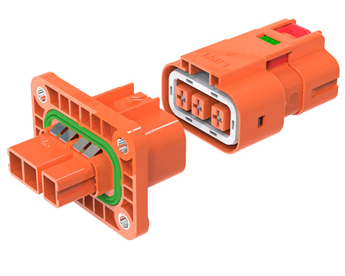
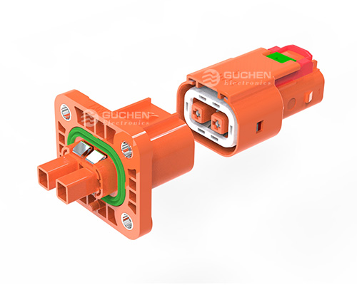
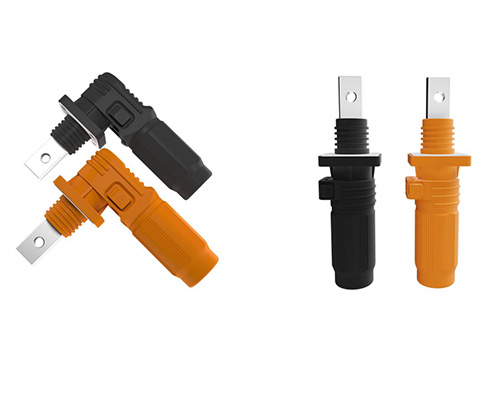
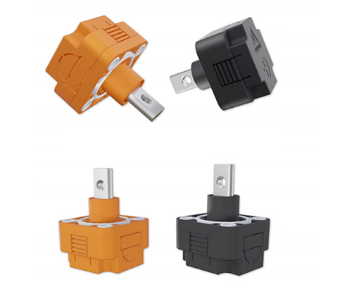
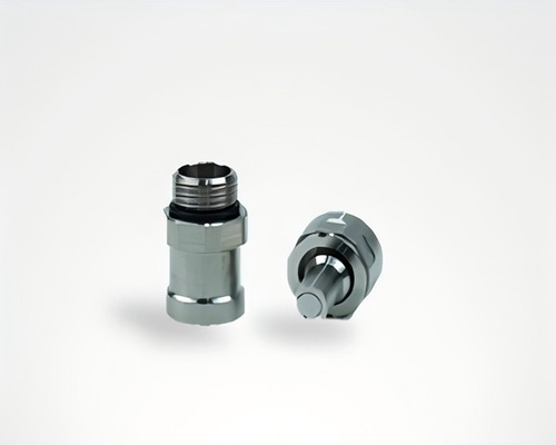
1.3 Basic Structure
An MSD primarily consists of two assemblies: the plug and the receptacle.--Receptacle
The receptacle is typically connected in series with the positive circuit of the battery pack and generally includes:
◆Busbar terminals
◆Fixed high-voltage contacts
◆High-voltage interlock (HVIL) contacts
--Plug
The plug assembly typically includes:
◆Moving high-voltage contacts
◆HVIL actuation pin
◆Operating handle
◆Locking mechanism
During maintenance, electrical isolation is achieved by removing the MSD plug.
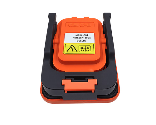
1.4 Main Types of MSD
MSDs are generally categorized into two types:
◆ Fused MSD
Provides both manual isolation and short-circuit protection through an integrated fuse.
◆ Non-Fused MSD
Provides manual isolation only and relies on external protection devices for overcurrent and short-circuit protection.
The primary difference lies in whether fuse protection is integrated within the MSD assembly:
| Comparison Item | MSD with Integrated Fuse | MSD without Fuse |
|---|---|---|
| Core Structure | Standard plug with an integrated DC fuse inside. Plug, contact terminals, and fuse are designed as a single integrated assembly. | Pure mechanical isolation switch without any fuse component, consisting only of conductive contacts, insulating housing, and locking mechanism. |
| Key Components | High-voltage contacts + built-in DC fuse + HVIL interlock + locking mechanism | High-voltage contacts + HVIL (High Voltage Interlock Loop) + HV lock + mechanical locking mechanism + insulating housing, without fuse |
| Protection Capability | Provides electrical isolation, short-circuit protection, and interruption of high fault currents. | Provides only physical high-voltage isolation; no overload or short-circuit protection function. |
| Primary Function | 1. Maintenance and mechanical isolation2. Battery cluster/string short-circuit fault protection through fuse operation | Used only for operation and maintenance (O&M) and troubleshooting as a means of physical isolation of the high-voltage circuit. |
| Arc Suppression Design | Equipped with DC arc-extinguishing media/chamber to withstand and interrupt short-duration fault currents. | No arc-extinguishing structure; strictly prohibited to insert or remove under load or while carrying current. |
| System Dependency | Can independently withstand and protect against strong short-circuit faults without relying on external fuses. | Requires protection from upstream high-voltage enclosure contactors and circuit breakers. |
| Safety Level | Higher safety level with dual protection (isolation + fuse protection). | Basic safety through contact separation only; no overload protection or fault-current interruption capability. |
| Operational Limitations | Allows no-load operation and can withstand instantaneous fault currents. | Must be operated only under complete circuit interruption and zero-current conditions. Live insertion/removal may cause arcing and contact damage. |
2. Installation and Removal Procedures for Battery String MSDs
2.1 Operating Principle
The entire operation should always be based on one core objective:◆ Minimizing the risk of electric shock and short circuits during maintenance activities.
This is achieved through strict adherence to the principle of Potential Gradient Control.
◆ During Removal (De-Energization)
Operate progressively from the highest-potential point to the lowest-potential point.
The high-voltage source is disconnected first, and each subsequent step continuously reduces the maximum voltage present in the remaining circuit, thereby minimizing risk.
◆ During Installation (Energization Preparation)
Operate progressively from the lowest-potential point to the highest-potential point.
The high-voltage source is intentionally kept disconnected until the final step, ensuring that the voltage level at each operating point remains as low as possible throughout the process.
2.2 Battery String Architecture
In a typical battery string, MSDs are installed in the positive circuit of each battery pack.The overall electrical configuration is as follows:
String Positive Terminal (Highest Potential)→ Pack 1 Positive → MSD → Pack 1 Negative
→ Pack 2 Positive → MSD → Pack 2 Negative
→ Pack 3 Positive → MSD → Pack 3 Negative
→ Pack 4 Positive → MSD → Pack 4 Negative
→ String Negative Terminal (Lowest Potential / System Ground Reference)
→ Connected to the Negative Circuit of the High-Voltage Distribution Unit
Potential Distribution
Pack 1 > Pack 2 > Pack 3 > Pack 4
where Pack 1 is closest to the string positive terminal and Pack 4 is closest to the string negative terminal.
2.3 Installation Sequence
Standard Installation Sequence(Progressing from Low Potential to High Potential)
Step 1: Install the MSD plug of Pack 4 (closest to the string negative terminal and at the lowest potential).
Step 2: Install the MSD plug of Pack 3 and verify full contact engagement and latch locking.
Step 3: Install the MSD plug of Pack 2 and verify full contact engagement and latch locking.
Step 4: Install the MSD plug of Pack 1 (closest to the string positive terminal and at the highest potential), and verify full contact engagement and latch locking.
Why This Sequence Is Recommended?
▷ The High-Voltage Source Remains Disconnected Until the Final Step
By starting from the lowest-potential side, the complete high-voltage source remains isolated throughout the installation process.
Until the final MSD of Pack 1 is installed, the full DC1500V string voltage is never connected, keeping operational risk at the lowest possible level.
▷ Prevents Premature Formation of a High-Voltage Circuit
If installation begins from Pack 1 on the positive side, the high-voltage source may be introduced into the circuit prematurely.
Subsequent MSD installation operations would then be performed at elevated potentials. Any accidental tool-to-ground contact or unintended circuit closure could result in:
◆High-voltage short circuits
◆Unexpected energization
◆Equipment damage
◆Personal injury
▷ Ensures Proper HVIL Operation
Installing MSDs from low potential to high potential ensures that the HVIL circuit is not fully completed until all main power contacts are properly engaged.
This prevents premature HVIL closure, which could cause the Battery Management System (BMS) to incorrectly interpret circuit status and potentially energize contactors before all power connections are fully established.
2.4 Removal Sequence
Standard Removal Sequence(Progressing from High Potential to Low Potential)
Step 1: Remove the MSD plug of Pack 1 (highest potential).
Step 2: Remove the MSD plug of Pack 2.
Step 3: Remove the MSD plug of Pack 3.
Step 4: Remove the MSD plug of Pack 4 (lowest potential).
Why This Sequence Is Recommended?
▷ Immediate Isolation of the High-Voltage Source
Removing the MSD closest to the string positive terminal immediately disconnects the highest-voltage source within the battery string.
With each subsequent MSD removal, the maximum voltage remaining in the circuit decreases by one battery pack voltage level, continuously reducing operational risk.
▷ Prevents High-Voltage Floating Conditions
If removal begins from Pack 4 on the negative side, the entire series-connected battery string may become electrically floating relative to system ground.
As a result, all subsequent operating points may remain at elevated voltages relative to ground, significantly increasing the risk of:
◆Electric shock
◆Ground-fault short circuits
◆Arc flash events
◆Fire hazards
▷ Forces HVIL Interlock Activation
The HVIL circuits of all MSDs are typically connected in series within the battery string safety loop.
The moment the first MSD is removed, the HVIL loop is interrupted, forcing the BMS to disable the high-voltage contactors and preventing accidental system energization.
2.5 Considerations for Servicing a Single MSD
When servicing the MSD of an individual battery pack, the following conditions must first be met:◆Complete system shutdown
◆Full isolation of the high-voltage cabinet
◆Verification of zero voltage
◆Confirmation that no backfeed voltage is present
Under normal conditions, it is unnecessary to remove the MSDs of other battery packs within the same string.
Only the target MSD needs to be operated to achieve physical isolation of the corresponding battery pack.
▷ Servicing Pack 1 (Highest-Potential Pack)
In rare cases where residual voltage discharge is uncertain, the MSD of Pack 4 may additionally be removed to establish a secondary physical isolation point and further reduce the energized area.
▷ Servicing a Middle Pack
Removing only the target MSD is sufficient to interrupt the series connection on both sides of the battery pack.
▷ Servicing Pack 4 (Lowest-Potential Pack)
Removing only the Pack 4 MSD is generally sufficient to achieve safe isolation.
The guiding principle is to minimize the scope of operation and avoid unnecessary MSD removal, thereby reducing the risk of contact damage, improper reconnection, and human error.
3. Important Notes
3.1 MSD Installed in the Negative Circuit
If the MSD is installed on the negative output side of the battery pack rather than the positive side, the core principle remains unchanged.Removal should still proceed from the battery pack closest to the string positive side toward the string negative side.
Installation should still proceed from the battery pack closest to the string negative side toward the string positive side.
The objective remains effective risk control through potential gradient management.
3.2 Additional Precautions for Non-Fused MSDs
Since non-fused MSDs do not provide short-circuit protection, the following conditions must be verified before installation:
◆No internal short circuit within any battery pack
◆Correct polarity
◆Acceptable voltage consistency among all battery packs
Failure to perform these checks may result in faults immediately after circuit connection.
3.3 Never Alter the Sequence
Installation and removal procedures must never be performed out of sequence.Before and after every operation, a properly rated high-voltage meter should be used to verify that measured voltages are as expected and that no abnormal energized conditions exist.
4. Conclusion
For any electrical operation, safety must always be the highest priority—especially when working with high-voltage systems, where a single mistake can lead to severe consequences.When installing or removing MSDs within a battery string, strict adherence to the principle of "Removal from High Potential to Low Potential, Installation from Low Potential to High Potential" helps minimize operational risk and enhances maintenance safety.
By following proper potential-gradient control practices, personnel can significantly reduce the likelihood of electric shock, short circuits, arc flash events, and unintended system energization during high-voltage battery maintenance operations.
Message
If you are interested in our products, please fill in the message form below. Our sales representative will contact you within 24 hours.