Liquid Cooling Server Components
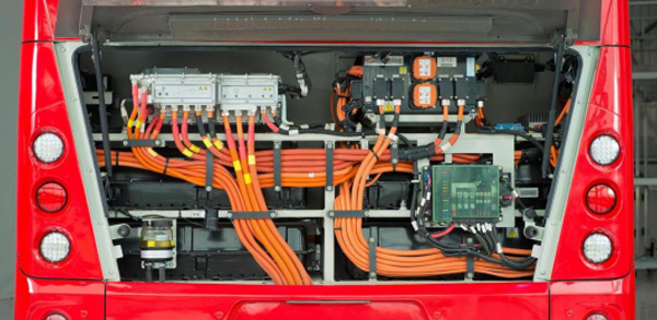
A liquid-cooled server is composed of multiple components working together. The following section introduces seven core components commonly found in both cold-plate and immersion liquid cooling systems.
Cold plates and quick disconnect couplings are unique to cold-plate liquid cooling systems, while the coolant reservoir is exclusive to immersion cooling. Coolants, Coolant Distribution Units (CDUs), primary-side cooling sources, and piping and valve assemblies are common to both types. Each component has distinct functions and performance requirements, which are explained in detail below.
In essence, the cold plate captures heat directly at the source and transfers it through liquid circulation, greatly enhancing cooling efficiency.
For low-power devices, CNC-etched channels or embedded metal tubes can be used. For high-power chips, fin-type (or microchannel) cold plates are commonly adopted — these feature densely machined grooves on the inner surface of the base plate to increase the heat exchange area.
Modern cold plate designs can handle the typical Thermal Design Power (TDP) of mainstream chips with additional safety margins, effectively cooling even next-generation GPUs exceeding 700W.
Compared to traditional air-cooled heat sinks, liquid-cooled cold plates transfer heat directly from the chip surface, reducing junction temperatures by 15–25°C and preventing thermal runaway in high-density computing environments.
The current market is dominated by single-phase cold plates, where the coolant does not undergo a phase change during operation. Deionized water or water-based solutions with anti-corrosion and antifreeze additives are typically used, making the system simple and reliable.
However, two-phase cold plates (also known as phase-change cold plates) have become a major research focus in recent years. These introduce low-boiling-point refrigerants inside the cold plate, which vaporize upon absorbing heat — removing a large amount of latent heat and significantly boosting cooling performance.
Two-phase designs also maintain a more uniform temperature across the chip contact surface, reducing temperature gradients. Nevertheless, because of vapor-liquid phase changes, they must manage rapid pressure fluctuations and prevent gas leakage, demanding higher pressure resistance and sealing integrity. This increases system cost and design complexity.
At present, two-phase cold plates are still in the R&D and small-scale testing phase. Many companies view them as a promising technology and are actively investing in overcoming related challenges.
In the future, with the adoption of new materials (such as high-thermal-conductivity silicon-based or nano-composite materials) and optimized flow channel designs, two-phase cold plates are expected to become practical solutions for dissipating heat from chips with even higher heat flux densities.
Water-based coolants typically use deionized water or formulated mixtures containing corrosion inhibitors and antifreeze agents. They offer excellent thermal conductivity and low cost but require an electrically isolated environment.
Non-water-based coolants, which contain no water, include hydrocarbon coolants (such as synthetic hydrocarbons or PAO synthetic oils), silicone-based coolants (silicone oils), and electronic fluorinated liquids (various perfluorinated compounds).
In cold-plate liquid cooling systems, the coolant circulates only within sealed cold plates and piping, without direct contact with electronic components. Therefore, water-based coolants usually meet the requirements (except for two-phase cold plates that use refrigerants). Most cold-plate liquid-cooled servers today use deionized water or ethylene glycol–water mixtures as the working fluid, with water-based coolants dominating the market thanks to their cost-effectiveness.
In contrast, immersion cooling systems submerge the entire server — including the motherboard and chips — directly in the coolant. This requires the fluid to have excellent electrical insulation and chemical stability, meaning only non-water-based coolants can be used.
Non-water-based coolants can be further categorized into two major groups:
◆ Oil-based coolants (e.g., synthetic hydrocarbon oils and silicone oils) — relatively low cost, but prone to viscosity increase and degradation at high temperatures.
◆ Electronic fluorinated liquids (also known as fluorocarbon or fluorinated refrigerants) — including perfluoropolyether (PFPE), perfluoroolefins, and hydrofluoroethers (HFEs). These fluids offer superior insulation, high thermal stability, and clean evaporation without residue, making them the most sought-after high-end coolants.
For instance, perfluoropolyether and hydrofluoroether fluids developed by companies such as 3M and Chemours are used in immersion or two-phase cold-plate cooling systems. They provide excellent insulation and heat transfer performance but are costly and limited in supply. Historically, the electronic fluorinated liquid market in China has been dominated by foreign suppliers, significantly increasing the overall system cost.
◆Thermal performance (specific heat capacity, thermal conductivity, and viscosity, all of which affect heat transfer efficiency),
◆Electrical properties (dielectric strength and insulation),
◆Material compatibility (compatibility with server components and sealing materials),
◆Environmental and safety aspects (flash point, toxicity, and global warming potential),
◆Cost.
Water-based coolants excel in heat transfer efficiency and cost but require corrosion and microbial control. Electronic fluorinated liquids deliver outstanding performance but are expensive, demand extremely high purity, and involve complex manufacturing processes.
At present, the market is dominated by single-phase cold-plate liquid cooling systems due to their simplicity and ease of maintenance — hence, water-based coolants remain the mainstream choice. However, as immersion cooling and two-phase cooling technologies advance, demand for high-performance coolants will grow rapidly, driving continuous innovation in material technologies.
Their function is similar to a “plug-and-play interface” in the pipeline, allowing server nodes to be serviced or replaced without draining the entire cooling circuit.

When mated, the two ends connect to form a continuous coolant passage; when disconnected, internal valves automatically close on both sides to prevent coolant leakage.
To meet on-site maintenance needs in data centers, QDs must be quick, reliable, and leak-free. Ideally, maintenance personnel should be able to disconnect or reconnect a server from the liquid cooling loop by hand, with no coolant spillage or air ingress during the operation.
Based on the connection method, liquid cooling QDs are divided into manual-mating and blind-mating types.
■ Manual-mating QDs include a locking mechanism and are connected or disconnected by hand. A typical example is the UQD series defined by the Open Compute Project (OCP) standard. Manufacturers such as Staubli, AVIC Optoelectronics, InVT, Nortown, and BlueCool have all released manual QDs based on the UQD specification. These connectors are structurally simple, technically mature, and cost-effective — making them the current mainstream choice in the market.
■ Blind-mating QDs, on the other hand, support automatic connection without manual intervention. They are designed so that the male and female couplings automatically engage when the server is inserted into the rack rail.
This design employs a floating alignment mechanism to ensure precise mating. The main advantage is ease of maintenance in high-density environments with limited space, where manual operation is difficult. Notable examples include the CGD series by Staubli, the TSF series by AVIC Optoelectronics, and the CQDB series by Huawei — all representing advanced solutions in the industry.
Currently, manual QDs still hold the largest market share due to their low cost and mature technology. However, as liquid-cooled data centers evolve toward higher density and automated maintenance, blind-mating QDs — with their space-saving and maintenance-friendly benefits — are expected to become standard in future high-density deployments.
Mechanically, they must ensure excellent sealing and durability — maintaining leak-free performance even after thousands of mating cycles and prolonged immersion in coolant without seal degradation.
Hydraulically, they should minimize flow resistance, featuring large flow diameters and smooth internal passages to avoid becoming bottlenecks in the cooling loop.
In addition, QDs must allow for reasonable mating length and axial tolerance compensation to accommodate installation variations during on-site assembly.
From an industry standard perspective, QDs from different manufacturers currently vary in dimensions, internal valve designs, and flow diameters, leading to poor interchangeability across brands. This lack of compatibility hampers system decoupling and large-scale deployment of liquid cooling infrastructure.
To address this, organizations such as the China Academy of Information and Communications Technology (CAICT) are leading efforts to establish standardized testing and performance benchmarks. Published works include Performance and Reliability Interchangeability Testing of Multi-Brand UQDs and the Research Report on Blind-Mating Liquid Cooling QD Development. The upcoming standard, Test Methods for Manual QDs in Cold-Plate Liquid Cooling Systems, aims to unify testing and design criteria.
The goal of standardization is to enable cross-vendor interoperability, promote decoupled supply models, and foster a healthy, competitive ecosystem.
With continuous advancements in both standards and technology, liquid cooling QDs are evolving toward higher reliability, greater flow capacity, and smarter functionality, becoming a key component for ensuring the safe and efficient operation of modern liquid cooling systems.
A CDU is typically designed in a cabinet or rack-mounted form, integrating key components such as a plate heat exchanger and circulation pumps within a compact structure.
The primary loop, which connects to the external cooling source (such as outdoor chillers or dry coolers), provides low-temperature coolant.
The secondary loop, which circulates through the servers, carries away heat from the electronic components.
As the coolant returns from the servers carrying heat, the plate heat exchanger transfers this heat to the primary loop. The primary loop then releases the heat into the environment through its external cooling source. Meanwhile, the CDU’s internal pump provides pressure and circulation power to keep the secondary loop flowing between the servers and the heat exchanger.
In addition to heat exchange, a CDU typically includes auxiliary components to ensure stable operation — such as expansion or pressure regulation tanks, make-up water systems, and air venting devices. Common configurations include a pressure vessel, water refill tank, automatic air release valve, and various sensors for leak detection, pressure, and temperature monitoring. These components help maintain pressure balance and operational safety in the secondary circuit.
▽ Rack-level (distributed) CDUs – compact units integrated within each server rack, serving that rack’s cooling loop.
▽ Cabinet-level (centralized) CDUs – larger units installed separately, capable of supplying coolant to multiple racks simultaneously.
 By the type of primary-side cooling medium, CDUs are further divided into:
▽ Air-to-liquid CDUs, which use air (via fans or dry coolers) to remove heat from the primary loop.
▽ Liquid-to-liquid CDUs, which use chilled water or cooling tower water for heat rejection.
Today’s market offers a wide variety of CDU products tailored for different use cases — including cold-plate, immersion, and air-cooled-to-liquid retrofits. Companies such as Vertiv, Inspur Information, and InVT have all launched specialized CDU solutions for various data center configurations.
● Improving Efficiency:
Manufacturers are optimizing internal piping materials, refining mechanical design, and improving processing precision to reduce flow resistance and increase heat exchange performance.
For example, Vertiv’s new-generation cold-plate CDU uses all-rigid piping instead of flexible hoses, minimizing bending losses, and features redesigned plate heat exchangers and pumps — resulting in lower system pressure drop and higher cooling capacity per unit volume.
Some suppliers have also introduced intelligent control strategies, using real-time monitoring data (temperature, pressure, flow rate) to predict load changes and dynamically adjust pump speeds and valve openings. This ensures on-demand cooling, improving efficiency under partial load conditions.
● Enhancing Safety:
Coolant leakage is one of the most critical risks in liquid cooling systems. To address this, innovative designs such as negative-pressure CDUs have emerged — pioneered by companies like Inspur Information.
These systems maintain a slight vacuum within the CDU and secondary loop using a vacuum pump, keeping the pressure below atmospheric level. In the event of a pipe rupture, air is drawn inward instead of coolant leaking outward, effectively preventing fluid leakage.
Even if a line connecting the server becomes detached, no coolant escapes, greatly improving system safety and reliability.
Such advancements will enable next-generation liquid-cooled data centers to achieve high-efficiency, safe, and intelligent thermal management, meeting the ever-increasing demands of high-density computing environments.
It serves as the “source cooling end” of the entire liquid-cooling loop.
Depending on the required supply water temperature, AI computing centers generally classify primary-side systems into high-temperature water systems (supply ≥ 35 °C) and low-temperature water systems (20 – 28 °C).
(Figure: Schematic Diagram of Primary and Secondary Sides in a Liquid Cooling System)
For high-temperature water scenarios, natural cooling can be fully utilized with little or no mechanical refrigeration. Common configurations include:
● Dry coolers (air-cooled radiators that use ambient air to cool the circulating water, suitable for cold and dry northern regions);
● Closed cooling towers (combining air and water heat exchange, applicable in humid areas with sufficient water resources);
● Open cooling tower + plate heat exchanger combinations (using an open tower for preliminary cooling, then a plate heat exchanger for closed-loop operation, ideal for sites with water sources and cost-sensitive projects).
These approaches rely on air cooling or water evaporation to achieve nearly 100% natural cooling, resulting in very low PUE values and significantly reduced energy consumption.
For low-temperature water scenarios, mechanical refrigeration becomes necessary due to the lower supply temperature requirements. Typical solutions include:
● Air-cooled chillers (compressor-based cooling with fan heat dissipation, often used in water-scarce northern regions), or
● Closed cooling tower + chiller combinations (used in hot and humid climates, with the cooling tower providing pre-cooling and the chiller offering supplemental cooling).
Since low-temperature systems involve compressors, their energy consumption is relatively higher.
Depending on local climate and computing density, AI data centers must balance energy efficiency, system reliability, and cost when selecting their primary-side cooling strategy.
For systems requiring mechanical refrigeration, several energy-saving technologies have been introduced, such as:
● Magnetic-bearing centrifugal chillers, which use frictionless magnetic bearings and variable-frequency drives to significantly improve part-load efficiency;
● Refrigerant pump dual-mode air conditioners (“fluorine pump” systems), which switch between two modes — when outdoor temperatures are suitable, the compressor shuts down and the refrigerant is circulated by pump for direct heat rejection (liquid-pump direct cooling); when temperatures rise, it automatically switches back to compressor cooling.
This flexible operation enables minimal power consumption across varying environmental conditions, and these technologies have already been commercialized and deployed in real-world projects.
In addition, integrating the primary-side system with clean energy and waste heat recovery is becoming a major trend — for instance, reusing data center waste heat for district heating or enhancing efficiency via heat pump technology.
Driven by government regulations, new data centers are increasingly required to achieve PUE < 1.3 or even below 1.25, pushing continuous innovation in primary-side cooling solutions.
In the future, liquid-cooled primary systems are expected to advance toward a higher proportion of natural cooling and lower refrigeration energy consumption, meeting stringent chip temperature demands while enabling greener and more sustainable computing infrastructure.
Its structural integrity and performance are crucial to the safe and stable operation of the entire system.
During operation, the tank is filled with a substantial volume of coolant. Servers are either horizontally placed (in single-phase immersion systems, usually open-top tanks) or vertically inserted (in two-phase immersion systems using phase-change cooling).
The tank is connected to the CDU (Coolant Distribution Unit) through piping, where the CDU’s pumps drive coolant circulation within the tank to remove heat generated by the servers.
In single-phase immersion cooling, the coolant remains in liquid state at all times. The tank can therefore be designed as an open structure, directly exposed to ambient air, simplifying refilling and maintenance.
In contrast, two-phase immersion systems involve the coolant boiling and producing vapor bubbles during heat absorption. As vapor forms, internal pressure rises, requiring the tank to be hermetically sealed and pressure-resistant to prevent gas leakage and coolant loss.
Without proper sealing, vapor escape not only leads to coolant depletion but may also pose health and environmental hazards.
Hence, two-phase tanks are typically equipped with reinforced sealing covers, pressure regulation devices, and often integrated condensers at the top to recover condensed refrigerant vapor.
Design Challenges and Improvements:
A major engineering challenge in immersion cooling is maintaining uniform flow distribution and temperature inside the tank.
Due to the dense server layout and concentrated heat loads, variations in liquid density can lead to uneven convection and localized “hot spots.”
To address this, several optimization strategies have been developed:
◆ Flow equalization plates installed at the tank bottom help distribute the incoming coolant evenly, suppress vortices and backflow, and balance flow across server nodes, reducing temperature differentials between layers.
◆ Vertical tank structures allow servers to be inserted upright into independent liquid compartments, minimizing thermal interference between nodes (a “multi-chamber” tank design).
In terms of materials and manufacturing, research is ongoing into high-strength composite materials and integrated forming processes to enhance structural strength, corrosion resistance, and sealing performance, while improving production efficiency.
Modern immersion cooling tanks have evolved beyond simple containers—they now integrate electrical distribution, refrigerant management, monitoring sensors, and maintenance aids into a single multifunctional platform.
Some designs feature built-in power busbars and network modules, as well as temperature and liquid-level sensors, lifting mechanisms, and inspection tools, making the cooling tank a fully functional micro liquid-cooling cabinet unit.
▽ LCM (Liquid Cooling Main loop) – the room-level supply and return headers;
▽ RCM (Rack Cooling Manifold) – the in-rack supply and return headers;
▽ Flexible hoses – connections between manifolds and server nodes.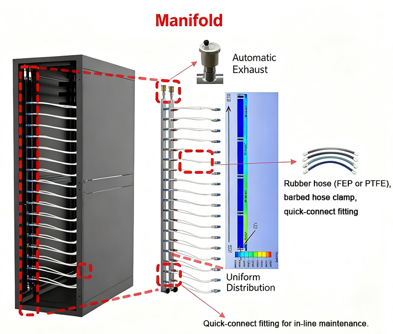 The LCM is usually installed beneath the raised floor or routed along the ceiling perimeter, functioning as the main trunk line that delivers coolant from the CDU to each rack or immersion tank and collects return flow.
LCMs are often arranged in ring networks with switch valves that allow directional changes and N+1 redundancy for reliability.
The RCM, located within each rack, typically includes one supply and one return manifold that distribute and collect coolant for all server nodes in the rack.
Each server connects to the RCM via quick-disconnect flexible hoses, enabling simple and secure coupling between the server and rack cooling circuits.
Air release valves are installed at high points along the LCM or RCM to eliminate trapped air and maintain system pressure stability.
The entire piping network integrates various valve assemblies, such as:
● Solenoid shutoff valves for rapid isolation during emergencies;
● Motorized control valves for temperature or flow-based regulation;
● Automatic switching valves for circuit redundancy or maintenance bypass.
These components enable precise control of coolant flow and safe system isolation under abnormal conditions.
Common materials include stainless steel, copper, and polymer composite tubing. Stainless steel is widely used for its strength and corrosion resistance, but internal surface roughness and weld cleanliness must be tightly controlled to minimize flow resistance and particle generation.
Flexible hose sections must combine durability, sealing reliability, and flexibility — typically using EPDM (ethylene-propylene-diene rubber) or hybrid structures of metal bellows with rubber layers, ensuring high temperature and pressure resistance while allowing easy installation and bending.
Valves act as the control core of the fluid circuit, demanding fast response, tight sealing, and reliability under frequent actuation without leakage or sticking.
In critical loops, dual redundant valves are often deployed to enhance reliability.
On the standardization side, the industry is promoting unified specifications for piping—covering cleanliness grades (to prevent clogging of cold plate channels), pressure ratings, nominal diameters and wall thicknesses, and fatigue life testing standards.
Such harmonization improves interoperability among components from different manufacturers, simplifying system integration and maintenance.
On the intelligentization side, as data centers move toward automated operation and maintenance, valves are evolving into smart actuators.
Next-generation smart valves integrate sensors and feedback mechanisms to monitor real-time parameters such as valve position, flow rate, and differential pressure, communicating with supervisory control systems for on-demand dynamic regulation.
Future smart valves may include embedded microprocessors and actuators with self-adaptive control, enabling more precise proportional adjustment, real-time environmental response, and automated flow optimization.
Through the combined advancement of standardized piping and intelligent valves, liquid cooling systems can achieve lower integration complexity, reduced O&M costs, and enhanced reliability and energy efficiency across large-scale data center deployments.
Cold plates and quick disconnect couplings are unique to cold-plate liquid cooling systems, while the coolant reservoir is exclusive to immersion cooling. Coolants, Coolant Distribution Units (CDUs), primary-side cooling sources, and piping and valve assemblies are common to both types. Each component has distinct functions and performance requirements, which are explained in detail below.
1 Cold Plate
The cold plate is the core heat dissipation component in a cold-plate liquid cooling server. It functions as a miniature heat exchanger that makes direct contact with heat-generating elements, effectively “attaching” to the chip surface for efficient heat transfer.Schematic Diagram of a Cold-Plate Liquid Cooling System
Operating Principle:
A cold plate consists of a base plate, a flow channel cover, and internal fluid passages. The base plate is tightly attached to high-power chips such as CPUs and GPUs. Through a thermal interface material, it transfers heat from the chip surface to the coolant flowing inside the channels. The cover and base plate are sealed to form an enclosed cavity with intricately designed flow channels, allowing the coolant to circulate and carry away heat.In essence, the cold plate captures heat directly at the source and transfers it through liquid circulation, greatly enhancing cooling efficiency.
Types and Performance:
Cold plates are mainly classified by structure and manufacturing process into stamped cold plates, CNC-machined cold plates, and embedded-tube cold plates.For low-power devices, CNC-etched channels or embedded metal tubes can be used. For high-power chips, fin-type (or microchannel) cold plates are commonly adopted — these feature densely machined grooves on the inner surface of the base plate to increase the heat exchange area.
Modern cold plate designs can handle the typical Thermal Design Power (TDP) of mainstream chips with additional safety margins, effectively cooling even next-generation GPUs exceeding 700W.
Compared to traditional air-cooled heat sinks, liquid-cooled cold plates transfer heat directly from the chip surface, reducing junction temperatures by 15–25°C and preventing thermal runaway in high-density computing environments.
Differences Between Air Cooling and Liquid Cooling Structures
Industry Status:
Cold plate technology is relatively mature, offering a wide range of structural designs and manufacturing techniques, and has been widely deployed in large-scale data centers.The current market is dominated by single-phase cold plates, where the coolant does not undergo a phase change during operation. Deionized water or water-based solutions with anti-corrosion and antifreeze additives are typically used, making the system simple and reliable.
However, two-phase cold plates (also known as phase-change cold plates) have become a major research focus in recent years. These introduce low-boiling-point refrigerants inside the cold plate, which vaporize upon absorbing heat — removing a large amount of latent heat and significantly boosting cooling performance.
Two-phase designs also maintain a more uniform temperature across the chip contact surface, reducing temperature gradients. Nevertheless, because of vapor-liquid phase changes, they must manage rapid pressure fluctuations and prevent gas leakage, demanding higher pressure resistance and sealing integrity. This increases system cost and design complexity.
At present, two-phase cold plates are still in the R&D and small-scale testing phase. Many companies view them as a promising technology and are actively investing in overcoming related challenges.
In the future, with the adoption of new materials (such as high-thermal-conductivity silicon-based or nano-composite materials) and optimized flow channel designs, two-phase cold plates are expected to become practical solutions for dissipating heat from chips with even higher heat flux densities.
2 Coolant
The coolant is the “blood” of a liquid-cooled server — it circulates through cold plates, piping, and other components to transfer heat, playing a vital role in both overall cooling performance and system safety.Types and Characteristics:
Based on chemical composition, coolants are generally divided into two categories: water-based and non-water-based coolants.Water-based coolants typically use deionized water or formulated mixtures containing corrosion inhibitors and antifreeze agents. They offer excellent thermal conductivity and low cost but require an electrically isolated environment.
Non-water-based coolants, which contain no water, include hydrocarbon coolants (such as synthetic hydrocarbons or PAO synthetic oils), silicone-based coolants (silicone oils), and electronic fluorinated liquids (various perfluorinated compounds).
In cold-plate liquid cooling systems, the coolant circulates only within sealed cold plates and piping, without direct contact with electronic components. Therefore, water-based coolants usually meet the requirements (except for two-phase cold plates that use refrigerants). Most cold-plate liquid-cooled servers today use deionized water or ethylene glycol–water mixtures as the working fluid, with water-based coolants dominating the market thanks to their cost-effectiveness.
In contrast, immersion cooling systems submerge the entire server — including the motherboard and chips — directly in the coolant. This requires the fluid to have excellent electrical insulation and chemical stability, meaning only non-water-based coolants can be used.
Immersion Cooling System Diagram
Non-water-based coolants can be further categorized into two major groups:
◆ Oil-based coolants (e.g., synthetic hydrocarbon oils and silicone oils) — relatively low cost, but prone to viscosity increase and degradation at high temperatures.
◆ Electronic fluorinated liquids (also known as fluorocarbon or fluorinated refrigerants) — including perfluoropolyether (PFPE), perfluoroolefins, and hydrofluoroethers (HFEs). These fluids offer superior insulation, high thermal stability, and clean evaporation without residue, making them the most sought-after high-end coolants.
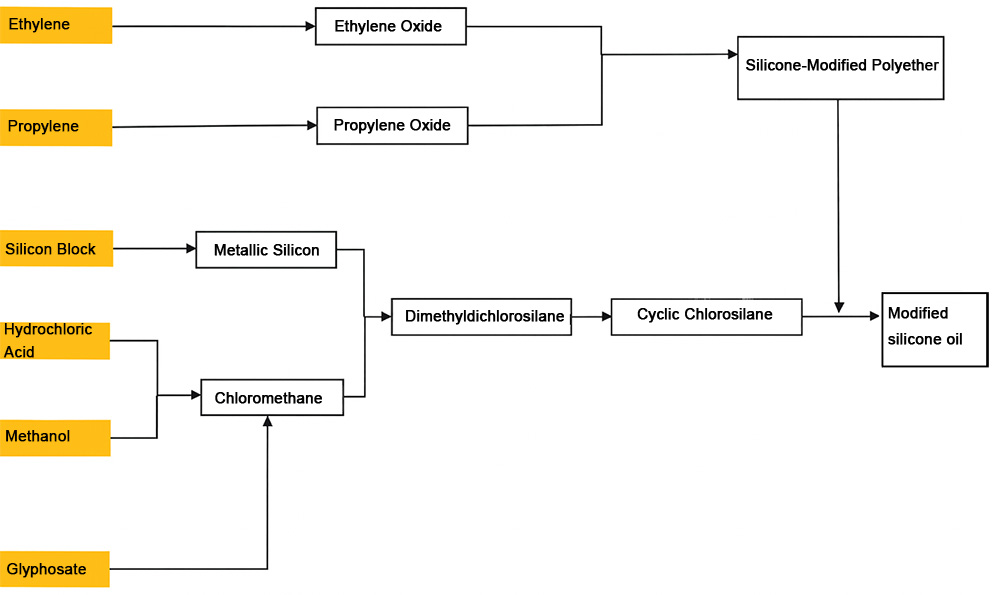
Industry Chain of Modified Silicone Oil Coolants
For instance, perfluoropolyether and hydrofluoroether fluids developed by companies such as 3M and Chemours are used in immersion or two-phase cold-plate cooling systems. They provide excellent insulation and heat transfer performance but are costly and limited in supply. Historically, the electronic fluorinated liquid market in China has been dominated by foreign suppliers, significantly increasing the overall system cost.
Key Performance Indicators:
Selecting an appropriate coolant requires balancing multiple factors, including:◆Thermal performance (specific heat capacity, thermal conductivity, and viscosity, all of which affect heat transfer efficiency),
◆Electrical properties (dielectric strength and insulation),
◆Material compatibility (compatibility with server components and sealing materials),
◆Environmental and safety aspects (flash point, toxicity, and global warming potential),
◆Cost.
Water-based coolants excel in heat transfer efficiency and cost but require corrosion and microbial control. Electronic fluorinated liquids deliver outstanding performance but are expensive, demand extremely high purity, and involve complex manufacturing processes.
At present, the market is dominated by single-phase cold-plate liquid cooling systems due to their simplicity and ease of maintenance — hence, water-based coolants remain the mainstream choice. However, as immersion cooling and two-phase cooling technologies advance, demand for high-performance coolants will grow rapidly, driving continuous innovation in material technologies.
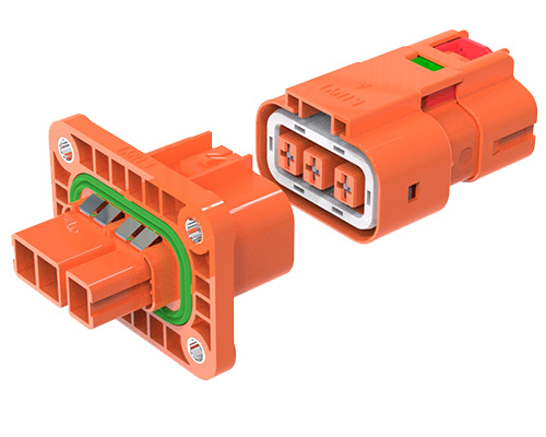
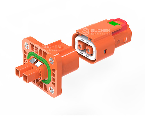
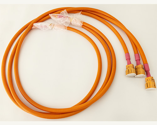
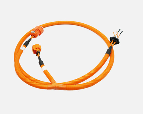
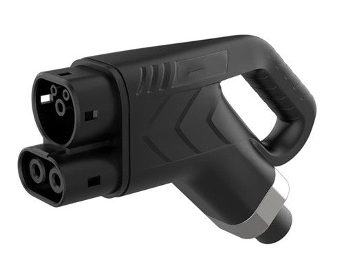
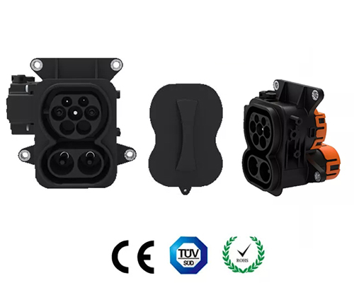
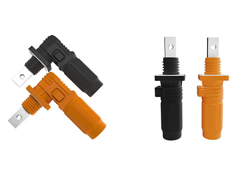
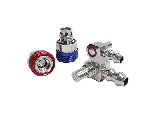
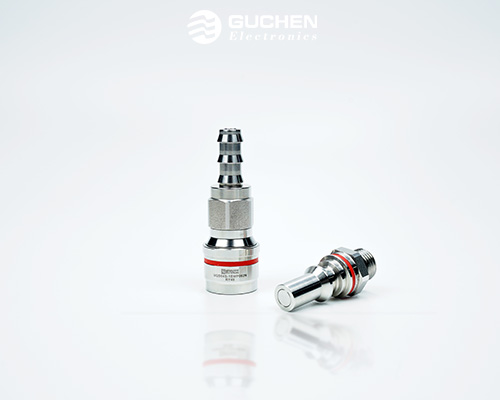
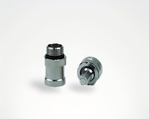
3 Quick Disconnect Couplings
Quick disconnect couplings (QDs) are essential connection components in a liquid cooling system. They connect the liquid-cooled server to the supply and return manifolds in the rack, enabling rapid connection and disconnection of coolant lines while maintaining a sealed flow path.Their function is similar to a “plug-and-play interface” in the pipeline, allowing server nodes to be serviced or replaced without draining the entire cooling circuit.
Structure and Function:
QDs are typically used in pairs — a male (plug) and a female (socket) part — mounted respectively on the server chassis and the rack manifold.When mated, the two ends connect to form a continuous coolant passage; when disconnected, internal valves automatically close on both sides to prevent coolant leakage.
To meet on-site maintenance needs in data centers, QDs must be quick, reliable, and leak-free. Ideally, maintenance personnel should be able to disconnect or reconnect a server from the liquid cooling loop by hand, with no coolant spillage or air ingress during the operation.
| Item | Manual Quick Connector | Direct Plug-In Connector |
| Reliability | Widely used in the market, mature technology, well-developed industrial chain, stable quality, and reliable manufacturers. | Newer technology with limited current market application; the technology is not yet fully mature and there are many manufacturers. |
| Flexibility | The hose length can be configured to provide more installation space and angle tolerance, resulting in higher flexibility. | Generally used for direct hose connection with stricter requirements on installation accuracy; flexibility is relatively lower. |
| Disassembly & Maintenance | The connection between the server and the cabinet is relatively flexible, making disassembly and maintenance easier. | The connection position between the server and the cabinet is fixed, making disassembly and maintenance more difficult. |
| Cost | Simple structure, smaller production difficulty, and relatively lower cost. | Requires precision machining and advanced manufacturing processes; more complex structure and higher cost compared to manual quick connectors. |
| Serviceability | Maintenance is relatively easy and convenient. | Maintenance is more complex. |
Table: Comparison Between Manual Quick Connector and Direct Plug-In Connector
Based on the connection method, liquid cooling QDs are divided into manual-mating and blind-mating types.
■ Manual-mating QDs include a locking mechanism and are connected or disconnected by hand. A typical example is the UQD series defined by the Open Compute Project (OCP) standard. Manufacturers such as Staubli, AVIC Optoelectronics, InVT, Nortown, and BlueCool have all released manual QDs based on the UQD specification. These connectors are structurally simple, technically mature, and cost-effective — making them the current mainstream choice in the market.
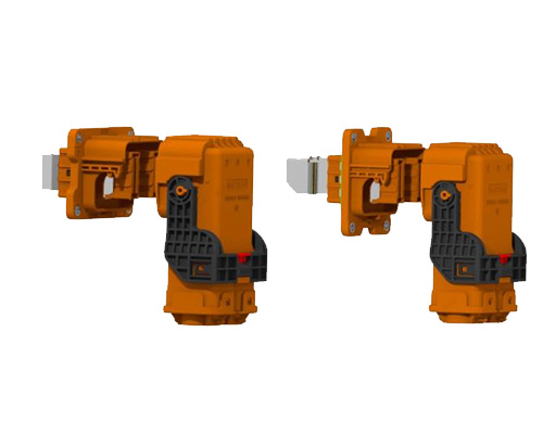
■ Blind-mating QDs, on the other hand, support automatic connection without manual intervention. They are designed so that the male and female couplings automatically engage when the server is inserted into the rack rail.
This design employs a floating alignment mechanism to ensure precise mating. The main advantage is ease of maintenance in high-density environments with limited space, where manual operation is difficult. Notable examples include the CGD series by Staubli, the TSF series by AVIC Optoelectronics, and the CQDB series by Huawei — all representing advanced solutions in the industry.
Currently, manual QDs still hold the largest market share due to their low cost and mature technology. However, as liquid-cooled data centers evolve toward higher density and automated maintenance, blind-mating QDs — with their space-saving and maintenance-friendly benefits — are expected to become standard in future high-density deployments.
Performance Requirements and Standardization:
Liquid cooling QDs must meet strict mechanical and fluid performance requirements.Mechanically, they must ensure excellent sealing and durability — maintaining leak-free performance even after thousands of mating cycles and prolonged immersion in coolant without seal degradation.
Hydraulically, they should minimize flow resistance, featuring large flow diameters and smooth internal passages to avoid becoming bottlenecks in the cooling loop.
In addition, QDs must allow for reasonable mating length and axial tolerance compensation to accommodate installation variations during on-site assembly.
From an industry standard perspective, QDs from different manufacturers currently vary in dimensions, internal valve designs, and flow diameters, leading to poor interchangeability across brands. This lack of compatibility hampers system decoupling and large-scale deployment of liquid cooling infrastructure.
To address this, organizations such as the China Academy of Information and Communications Technology (CAICT) are leading efforts to establish standardized testing and performance benchmarks. Published works include Performance and Reliability Interchangeability Testing of Multi-Brand UQDs and the Research Report on Blind-Mating Liquid Cooling QD Development. The upcoming standard, Test Methods for Manual QDs in Cold-Plate Liquid Cooling Systems, aims to unify testing and design criteria.
The goal of standardization is to enable cross-vendor interoperability, promote decoupled supply models, and foster a healthy, competitive ecosystem.
With continuous advancements in both standards and technology, liquid cooling QDs are evolving toward higher reliability, greater flow capacity, and smarter functionality, becoming a key component for ensuring the safe and efficient operation of modern liquid cooling systems.
4 Cooling Distribution Unit (CDU)
The Cooling Distribution Unit (CDU) serves as the thermal exchange center and power hub of a liquid cooling system. It is responsible for heat exchange between the primary and secondary cooling loops, as well as for regulating and distributing coolant flow throughout the system.A CDU is typically designed in a cabinet or rack-mounted form, integrating key components such as a plate heat exchanger and circulation pumps within a compact structure.
Working Principle:
The CDU transfers heat via the plate heat exchanger between two coolant circuits:The primary loop, which connects to the external cooling source (such as outdoor chillers or dry coolers), provides low-temperature coolant.
The secondary loop, which circulates through the servers, carries away heat from the electronic components.
As the coolant returns from the servers carrying heat, the plate heat exchanger transfers this heat to the primary loop. The primary loop then releases the heat into the environment through its external cooling source. Meanwhile, the CDU’s internal pump provides pressure and circulation power to keep the secondary loop flowing between the servers and the heat exchanger.
In addition to heat exchange, a CDU typically includes auxiliary components to ensure stable operation — such as expansion or pressure regulation tanks, make-up water systems, and air venting devices. Common configurations include a pressure vessel, water refill tank, automatic air release valve, and various sensors for leak detection, pressure, and temperature monitoring. These components help maintain pressure balance and operational safety in the secondary circuit.
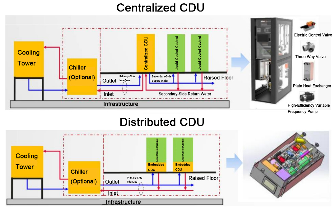
Configuration Types:
Based on installation layout, CDUs can be categorized into:▽ Rack-level (distributed) CDUs – compact units integrated within each server rack, serving that rack’s cooling loop.
▽ Cabinet-level (centralized) CDUs – larger units installed separately, capable of supplying coolant to multiple racks simultaneously.
▽ Air-to-liquid CDUs, which use air (via fans or dry coolers) to remove heat from the primary loop.
▽ Liquid-to-liquid CDUs, which use chilled water or cooling tower water for heat rejection.
Today’s market offers a wide variety of CDU products tailored for different use cases — including cold-plate, immersion, and air-cooled-to-liquid retrofits. Companies such as Vertiv, Inspur Information, and InVT have all launched specialized CDU solutions for various data center configurations.
| Item | Centralized CDU | Distributed CDU |
| Layout | The CDU is installed outside the rack. Typically, one CDU serves two to three racks. | The CDU is installed inside the rack, with one CDU dedicated to each rack. |
| Piping Connection | More piping is required; one side requires dual piping. It is necessary to consider the number of times the coolant passes through the CDU. | Single-pass piping directly enters each liquid-cooled rack. |
| Space Utilization | Centrally arranged in the equipment room or air-conditioning zone; does not occupy rack space. | Integrated inside the rack; occupies rack U-space. |
| Maintainability | Relatively simple; in case of failure, centralized shutdown and maintenance are required. | Relatively complex; multi-point shutdown and maintenance are required. |
| Reliability | N+X redundancy configuration available, offering high reliability. | One-to-one with each rack; usually configured with pump 1+1 redundancy, with lower overall system reliability. |
| Application Scenarios | Suitable for medium to large and hyperscale data centers with a large number of racks. Widely used and easy to maintain. | Suitable for small data centers; not suitable for medium and large or hyperscale data centers, as it increases maintenance workload. |
| Technology Maturity | Highly mature, with an early market adoption and wide application. | Later market adoption; currently in the innovation and early application stage. |
| Failure Impact Scope | Wide impact range; a failure may affect multiple racks simultaneously. | Narrow impact range; a failure only affects a single rack. |
Table: Comparison Between Centralized CDU and Distributed CDU
Technology Development Trends:
As the core component of a liquid cooling system, CDU innovation primarily focuses on enhancing heat exchange efficiency and improving leak prevention and safety.● Improving Efficiency:
Manufacturers are optimizing internal piping materials, refining mechanical design, and improving processing precision to reduce flow resistance and increase heat exchange performance.
For example, Vertiv’s new-generation cold-plate CDU uses all-rigid piping instead of flexible hoses, minimizing bending losses, and features redesigned plate heat exchangers and pumps — resulting in lower system pressure drop and higher cooling capacity per unit volume.
Some suppliers have also introduced intelligent control strategies, using real-time monitoring data (temperature, pressure, flow rate) to predict load changes and dynamically adjust pump speeds and valve openings. This ensures on-demand cooling, improving efficiency under partial load conditions.
● Enhancing Safety:
Coolant leakage is one of the most critical risks in liquid cooling systems. To address this, innovative designs such as negative-pressure CDUs have emerged — pioneered by companies like Inspur Information.
These systems maintain a slight vacuum within the CDU and secondary loop using a vacuum pump, keeping the pressure below atmospheric level. In the event of a pipe rupture, air is drawn inward instead of coolant leaking outward, effectively preventing fluid leakage.
Even if a line connecting the server becomes detached, no coolant escapes, greatly improving system safety and reliability.
Future Outlook:
Looking ahead, CDUs will continue to evolve toward higher integration, intelligence, and reliability — featuring more compact designs, precise flow control, and smart monitoring functions that integrate with data center operation systems.Such advancements will enable next-generation liquid-cooled data centers to achieve high-efficiency, safe, and intelligent thermal management, meeting the ever-increasing demands of high-density computing environments.
5 Primary-Side System
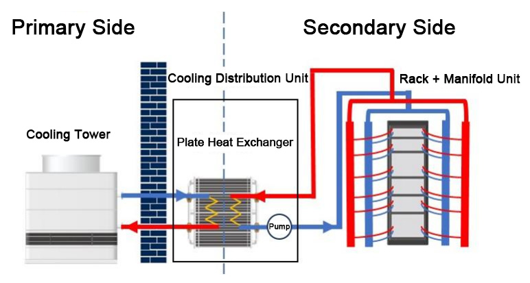
The primary-side system refers to the outdoor cooling source and its auxiliary facilities in a liquid-cooled data center — the equipment that produces the cooling water or coolant supplied to the CDU.It serves as the “source cooling end” of the entire liquid-cooling loop.
Composition and Classification:
A primary-side system typically includes outdoor cooling equipment (such as cooling towers, dry coolers, or chillers), along with pumps and pipelines that deliver chilled liquid to the indoor CDU.Depending on the required supply water temperature, AI computing centers generally classify primary-side systems into high-temperature water systems (supply ≥ 35 °C) and low-temperature water systems (20 – 28 °C).
(Figure: Schematic Diagram of Primary and Secondary Sides in a Liquid Cooling System)
For high-temperature water scenarios, natural cooling can be fully utilized with little or no mechanical refrigeration. Common configurations include:
● Dry coolers (air-cooled radiators that use ambient air to cool the circulating water, suitable for cold and dry northern regions);
● Closed cooling towers (combining air and water heat exchange, applicable in humid areas with sufficient water resources);
● Open cooling tower + plate heat exchanger combinations (using an open tower for preliminary cooling, then a plate heat exchanger for closed-loop operation, ideal for sites with water sources and cost-sensitive projects).
These approaches rely on air cooling or water evaporation to achieve nearly 100% natural cooling, resulting in very low PUE values and significantly reduced energy consumption.
For low-temperature water scenarios, mechanical refrigeration becomes necessary due to the lower supply temperature requirements. Typical solutions include:
● Air-cooled chillers (compressor-based cooling with fan heat dissipation, often used in water-scarce northern regions), or
● Closed cooling tower + chiller combinations (used in hot and humid climates, with the cooling tower providing pre-cooling and the chiller offering supplemental cooling).
| Chilled Water Temperature Level | Inlet Water Temperature (One Side) | Cooling Source Configuration |
| W17 | 17°C | Chiller unit, assisted by a water economizer (plate heat exchanger) |
| W27 | 27°C | Chiller unit, assisted by a water economizer (plate heat exchanger) |
| W32 | 32°C | Cooling tower or dry cooler, assisted by chiller unit or district heat recovery system |
| W40 | 40°C | Cooling tower or dry cooler, assisted by chiller unit or district heat recovery system |
| W45 | 45°C | Cooling tower or dry cooler, assisted by district heat recovery system |
| W+ | >45°C | Cooling tower or dry cooler, assisted by district heat recovery system |
| Note: The minimum supply water temperature should not be lower than 2°C. | ||
Table: Cooling Source Configurations for Different Primary-Side Supply Temperature Levels
Since low-temperature systems involve compressors, their energy consumption is relatively higher.
Depending on local climate and computing density, AI data centers must balance energy efficiency, system reliability, and cost when selecting their primary-side cooling strategy.
Technological Evolution:
As the scale of liquid-cooled computing centers expands, the primary-side cooling source continues to evolve toward higher efficiency and sustainability.For systems requiring mechanical refrigeration, several energy-saving technologies have been introduced, such as:
● Magnetic-bearing centrifugal chillers, which use frictionless magnetic bearings and variable-frequency drives to significantly improve part-load efficiency;
● Refrigerant pump dual-mode air conditioners (“fluorine pump” systems), which switch between two modes — when outdoor temperatures are suitable, the compressor shuts down and the refrigerant is circulated by pump for direct heat rejection (liquid-pump direct cooling); when temperatures rise, it automatically switches back to compressor cooling.
This flexible operation enables minimal power consumption across varying environmental conditions, and these technologies have already been commercialized and deployed in real-world projects.
In addition, integrating the primary-side system with clean energy and waste heat recovery is becoming a major trend — for instance, reusing data center waste heat for district heating or enhancing efficiency via heat pump technology.
Driven by government regulations, new data centers are increasingly required to achieve PUE < 1.3 or even below 1.25, pushing continuous innovation in primary-side cooling solutions.
In the future, liquid-cooled primary systems are expected to advance toward a higher proportion of natural cooling and lower refrigeration energy consumption, meeting stringent chip temperature demands while enabling greener and more sustainable computing infrastructure.
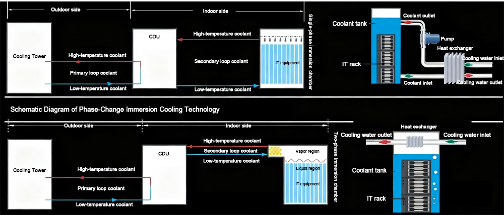
6 Cooling Tank
The cooling tank is a fundamental component unique to immersion liquid cooling systems. It serves as the vessel that holds the coolant and houses the IT equipment—essentially the container in which the servers are “immersed in liquid.”Its structural integrity and performance are crucial to the safe and stable operation of the entire system.
Structure and Function:
The cooling tank is typically made of durable metallic materials, with a common design consisting of a stainless steel or aluminum alloy inner liner supported by an external steel frame, forming a large open or sealed liquid reservoir.During operation, the tank is filled with a substantial volume of coolant. Servers are either horizontally placed (in single-phase immersion systems, usually open-top tanks) or vertically inserted (in two-phase immersion systems using phase-change cooling).
The tank is connected to the CDU (Coolant Distribution Unit) through piping, where the CDU’s pumps drive coolant circulation within the tank to remove heat generated by the servers.
In single-phase immersion cooling, the coolant remains in liquid state at all times. The tank can therefore be designed as an open structure, directly exposed to ambient air, simplifying refilling and maintenance.
Figure: Principle Diagram of Single-Phase Immersion Liquid Cooling Technology
In contrast, two-phase immersion systems involve the coolant boiling and producing vapor bubbles during heat absorption. As vapor forms, internal pressure rises, requiring the tank to be hermetically sealed and pressure-resistant to prevent gas leakage and coolant loss.
Without proper sealing, vapor escape not only leads to coolant depletion but may also pose health and environmental hazards.
Hence, two-phase tanks are typically equipped with reinforced sealing covers, pressure regulation devices, and often integrated condensers at the top to recover condensed refrigerant vapor.
Design Challenges and Improvements:
A major engineering challenge in immersion cooling is maintaining uniform flow distribution and temperature inside the tank.
Due to the dense server layout and concentrated heat loads, variations in liquid density can lead to uneven convection and localized “hot spots.”
To address this, several optimization strategies have been developed:
◆ Flow equalization plates installed at the tank bottom help distribute the incoming coolant evenly, suppress vortices and backflow, and balance flow across server nodes, reducing temperature differentials between layers.
◆ Vertical tank structures allow servers to be inserted upright into independent liquid compartments, minimizing thermal interference between nodes (a “multi-chamber” tank design).
In terms of materials and manufacturing, research is ongoing into high-strength composite materials and integrated forming processes to enhance structural strength, corrosion resistance, and sealing performance, while improving production efficiency.
Modern immersion cooling tanks have evolved beyond simple containers—they now integrate electrical distribution, refrigerant management, monitoring sensors, and maintenance aids into a single multifunctional platform.
Some designs feature built-in power busbars and network modules, as well as temperature and liquid-level sensors, lifting mechanisms, and inspection tools, making the cooling tank a fully functional micro liquid-cooling cabinet unit.
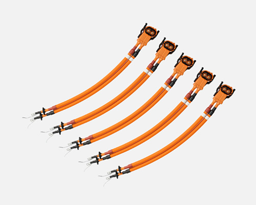
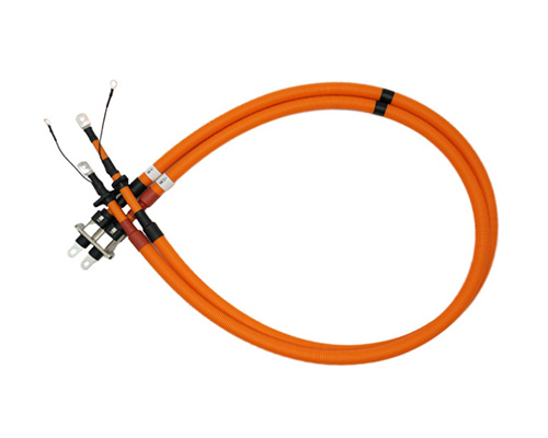
7 Liquid Cooling Piping and Valve Assemblies
The liquid cooling piping and valve assemblies serve as the “vascular system and control valves” of a liquid cooling setup, forming a complete network for coolant transport and regulation.Composition and Layout:
In a data center, the piping system is typically divided into three hierarchical levels:▽ LCM (Liquid Cooling Main loop) – the room-level supply and return headers;
▽ RCM (Rack Cooling Manifold) – the in-rack supply and return headers;
▽ Flexible hoses – connections between manifolds and server nodes.
LCMs are often arranged in ring networks with switch valves that allow directional changes and N+1 redundancy for reliability.
The RCM, located within each rack, typically includes one supply and one return manifold that distribute and collect coolant for all server nodes in the rack.
Each server connects to the RCM via quick-disconnect flexible hoses, enabling simple and secure coupling between the server and rack cooling circuits.
Air release valves are installed at high points along the LCM or RCM to eliminate trapped air and maintain system pressure stability.
The entire piping network integrates various valve assemblies, such as:
● Solenoid shutoff valves for rapid isolation during emergencies;
● Motorized control valves for temperature or flow-based regulation;
● Automatic switching valves for circuit redundancy or maintenance bypass.
These components enable precise control of coolant flow and safe system isolation under abnormal conditions.
Performance Requirements:
Piping materials must withstand sustained pressure and continuous contact with the coolant, requiring excellent pressure resistance, corrosion protection, and cleanliness.Common materials include stainless steel, copper, and polymer composite tubing. Stainless steel is widely used for its strength and corrosion resistance, but internal surface roughness and weld cleanliness must be tightly controlled to minimize flow resistance and particle generation.
Flexible hose sections must combine durability, sealing reliability, and flexibility — typically using EPDM (ethylene-propylene-diene rubber) or hybrid structures of metal bellows with rubber layers, ensuring high temperature and pressure resistance while allowing easy installation and bending.
Valves act as the control core of the fluid circuit, demanding fast response, tight sealing, and reliability under frequent actuation without leakage or sticking.
In critical loops, dual redundant valves are often deployed to enhance reliability.
Innovation Trends:
The development of liquid cooling piping and valve assemblies is advancing toward standardization and intelligent control.On the standardization side, the industry is promoting unified specifications for piping—covering cleanliness grades (to prevent clogging of cold plate channels), pressure ratings, nominal diameters and wall thicknesses, and fatigue life testing standards.
Such harmonization improves interoperability among components from different manufacturers, simplifying system integration and maintenance.
On the intelligentization side, as data centers move toward automated operation and maintenance, valves are evolving into smart actuators.
Next-generation smart valves integrate sensors and feedback mechanisms to monitor real-time parameters such as valve position, flow rate, and differential pressure, communicating with supervisory control systems for on-demand dynamic regulation.
Future smart valves may include embedded microprocessors and actuators with self-adaptive control, enabling more precise proportional adjustment, real-time environmental response, and automated flow optimization.
Through the combined advancement of standardized piping and intelligent valves, liquid cooling systems can achieve lower integration complexity, reduced O&M costs, and enhanced reliability and energy efficiency across large-scale data center deployments.
Message
If you are interested in our products, please fill in the message form below. Our sales representative will contact you within 24 hours.